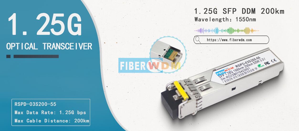
1.25G SFP optical transceiver module, support 1.25Gb/s 200 km transmission, It works in high-speed IDC connection solutions, network switch, PTN, OTN and so on.
Features:
Applications:
RSPD-03S200-55
1.25Gb/s 200km SFP Transceiver Hot Pluggable, Duplex LC, +3.3V, 1550nm, DFB-LD &APD, Single-mode, DDM
FIBERWDM’s RSPD-03S200-55 1.25G 200KM SFP Transceiver is a high performance, cost-effective module which have aduplex LC optics interface. Standard AC coupled CML for high speed signal and LVTTL control and monitor signals. The receiver section uses an APD receiver and the transmitter uses a 1550 nmDFB laser, up to 42dB link budge ensure this module 1000Base Ethernet 200km application.

Absolute Maximum Ratings
|
Parameter |
Symbol |
Min. |
Typical |
Max. |
Unit |
|
StorageTemperature |
TS |
-40 |
|
+85 |
°C |
|
SupplyVoltage |
VCC |
-0.5 |
|
4 |
V |
|
RelativeHumidity |
RH |
0 |
|
85 |
% |
Recommended Operating Environment:
|
Parameter |
Symbol |
Min. |
Typical |
Max. |
Unit |
|
|
CaseoperatingTemperature |
Industrial |
TC |
-40 |
|
85 |
°C |
|
Extended |
-5 |
|
85 |
°C |
||
|
Commercial |
0 |
|
+70 |
°C |
||
|
SupplyVoltage |
VCC |
3.1 |
|
3.6 |
V |
|
|
Supply Current |
Icc |
|
|
300 |
mA |
|
|
Inrush Current |
Isurge |
|
|
Icc+30 |
mA |
|
|
Maximum Power |
Pmax |
|
|
1 |
W |
|
Electrical Characteristics(TOP =-30 to70°C, VCC = 3.1 to 3.65Volts)
|
Parameter |
Symbol |
Min. |
Typical |
Max. |
Unit |
Note |
|
Transmitter Section: |
|
|||||
|
Input differential impedance |
Rin |
90 |
100 |
110 |
W |
1 |
|
Single ended data input swing |
Vin PP |
250 |
|
1200 |
mVp-p |
|
|
Transmit Disable Voltage |
VD |
Vcc – 1.3 |
|
Vcc |
V |
2 |
|
Transmit Enable Voltage |
VEN |
Vee |
|
Vee+ 0.8 |
V |
|
|
Transmit Disable Assert Time |
Tdessert |
|
|
10 |
us |
|
|
Receiver Section: |
|
|||||
|
Single ended data output swing |
Vout,pp |
250 |
|
800 |
mv |
3 |
|
LOS Fault |
Vlosfault |
Vcc – 0.5 |
|
VCC_host |
V |
5 |
|
LOS Normal |
Vlos norm |
Vee |
|
Vee+0.5 |
V |
5 |
|
Power Supply Rejection |
PSR |
100 |
|
|
mVpp |
6 |
Note:
1. AC coupled.
2. Or open circuit.
3. Into 100 ohm differential termination.
4. 20 – 80 %
5. LOS is LVTTL. Logic 0 indicates normal operation; logic 1 indicates no signal detected.
6. All transceiver specifications are compliant with a power supply sinusoidal modulation of 20 Hz to 1.5MHz up to specified value applied through the power supply filtering network shown on page 23 of the Small Form-factor Pluggable (SFP) Transceiver Multi-Source Agreement (MSA), September 14, 2000.
Optical Parameters(TOP =-30 to70°C, VCC = 3.1 to 3.6 Volts)
|
Parameter |
Symbol |
Min. |
Typical |
Max. |
Unit |
Note |
|
Transmitter Section: |
||||||
|
Center Wavelength |
λc |
1530 |
1550 |
1570 |
nm |
|
|
Spectral Width |
σ |
|
|
1 |
nm |
|
|
Side Mode Suppression Ratio |
SMSR |
30 |
|
|
dB |
|
|
Optical Output Power |
Pout |
+3 |
|
+7 |
dBm |
1 |
|
Extinction Ratio |
ER |
9 |
|
|
dB |
|
|
Optical Rise/Fall Time |
tr / tf |
|
|
260 |
ps |
2 |
|
Relative Intensity Noise |
RIN |
|
|
-120 |
dB/Hz |
|
|
Output Eye Mask |
Compliant with IEEE802.3 z (class 1 laser safety) |
|
||||
|
Receiver Section: |
|
|||||
|
Optical Input Wavelength |
λc |
1270 |
|
1610 |
nm |
|
|
ReceiverOverload |
Pol |
-7 |
|
|
dBm |
4 |
|
RXSensitivity |
Sen |
|
|
-37 |
dBm |
4 |
|
RX_LOS Assert |
LOS A |
-46 |
|
|
dBm |
|
|
RX_LOS De-assert |
LOS D |
|
|
-39 |
dBm |
|
|
RX_LOS Hysteresis |
LOSH |
0.5 |
|
|
dB |
|
|
General Specifications: |
||||||
|
Data Rate |
BR |
|
1.25 |
|
Gb/s |
|
|
Bit Error Rate |
BER |
|
|
10-12 |
|
|
|
Max. Supported Link Length on9/125μmSMF@1.25Gb/s |
LMAX |
|
|
200 |
km |
|
|
Total System Budget |
LB |
40 |
|
|
dB |
|
Note
1. The optical power is launched intoSMF.
2. 20-80%.
3. Jitter measurements taken using Agilent OMNIBERT 718 in accordance with GR-253.
4. Measured with PRBS 27-1 at 10-12 BER
想知道这个产品吗?
如果您对我们的产品感兴趣并想了解更多详细信息,请在此处留言,我们将尽快答复您。